This DIY is over 30 pages long so I won't post the whole thing here.
Here is a link to a PDF version of the DIY: PDF
Here is the first section of that PDF:
After considering all the WM kits I decided on the DO Stage 2 kit.
The Snow performance was 2nd place but in the end I decided on MAP controlled over MAF controlled because the temperature in my city can change drastically in a matter of hours. The free check valve, a metal nozzle holder and black tubing are also a plus.
I considered the AEM kit but I did not want to run any boost lines, I’d rather have it electronic.
I wanted the install to be as clean and stealth as possible, I didn’t want any exposed wires, no fuse holders visible, etc. I opted to solder all the connection instead of using the Posi-Lock connectors.
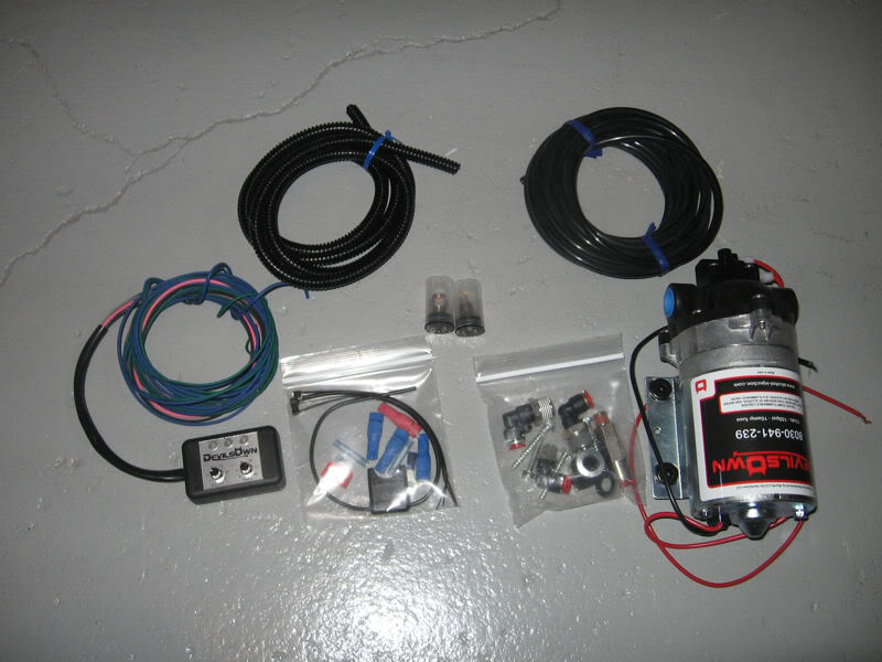
Devils Own Stage 2 WM kit 2.5bar:
Stage 1, Wiring:
Tools:
T25
T30
8mm socket
10mm socket
13mm socket
Electrical Tape
Soldering Iron
Tweezers
Pointy tool
Parts:
Repair wire 000 979 242
Zip tie
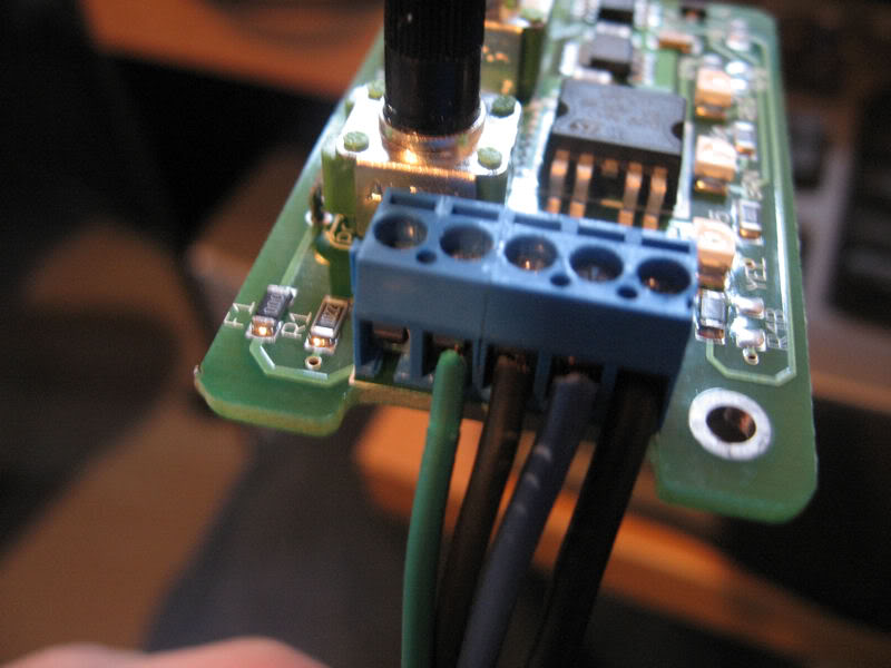
Step 1, Prepare the controller:
The gray wire is not needed as I plan on using the MAP sensor on the engine instead of using an external Map sensor:
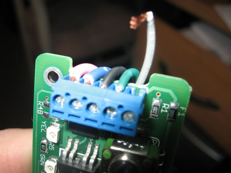
The pink power wire was not long enough so I switched it to a longer 16 gauge wire. From here on in the pink wire will be black:
ttp://i597.photobucket.com/albums/tt53/cadbury204/WM/IMG_2946.jpg[/IMG]
Step 2, Remove battery and tray:
The removal of the battery is self explanatory. You will need a 10mm wrench/socket to remove the cables from the battery. Always remember to remove the negative side first. The bracket that holds the battery down is 13mm (blue).
Once the battery is removed you will need to remove the tray it sits on. There are 3 bolts (red). In the picture below one bolt is not pictured:

Tray removed:

Step 3, Remove relay panel:
First remove the positive wires from the relay panel. You will need a 10mm socket (red) and an 8mm socket (blue):

Unscrew the T30 screw (red) and the panel should pop off. We will be adding a fuse in F23 (blue):
When I pulled the relay panel off I was working blind I wasn’t sure how this was going to turn out. I had an extra repair wire from when I installed my alarm siren and I found a connector on the back of the panel that fit the repair wire perfectly. I probed around with a multimeter for a few seconds and I found that the fuse above (Blue) connected to the pin 15 on the connector below the panel below (red). This is where I decided to add the 10amp fuse that came with the DO kit.
Step 4, Add repair wire:
This is the spot where we will add the repair wire. You will need to push the pink clip (blue) in the direction of the arrow:
Push out the green water tight plug with the tweezers:
Add silicone to the wire to ensure everything is water tight and insert from the bottom side. VW wanted this panel to stay water tight so once I had the wire in there I double checked that the new wire was indeed water tight. Once completed push the pink clip (2 pictures back) back to its original position:

Step 5, Run wires through firewall:
This is the rubber gasket where we will run the wires. It’s located behind where the battery used to be:
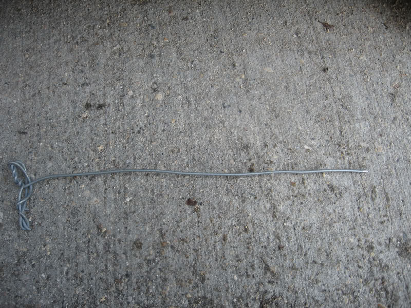
Use a long pointy tool and push it through the gasket. You will need to remove the black panel above the pedals to see the gasket from the inside. Remove these 2 screws (red), they are both T25:

The tool:
Wires pulled through from outside:

Wires on the inside:

Step 6, Run wires inside engine compartment:
Put the 3 wires into the wire loom supplied with the DO kit and run it next to the other wiring harnesses (red):
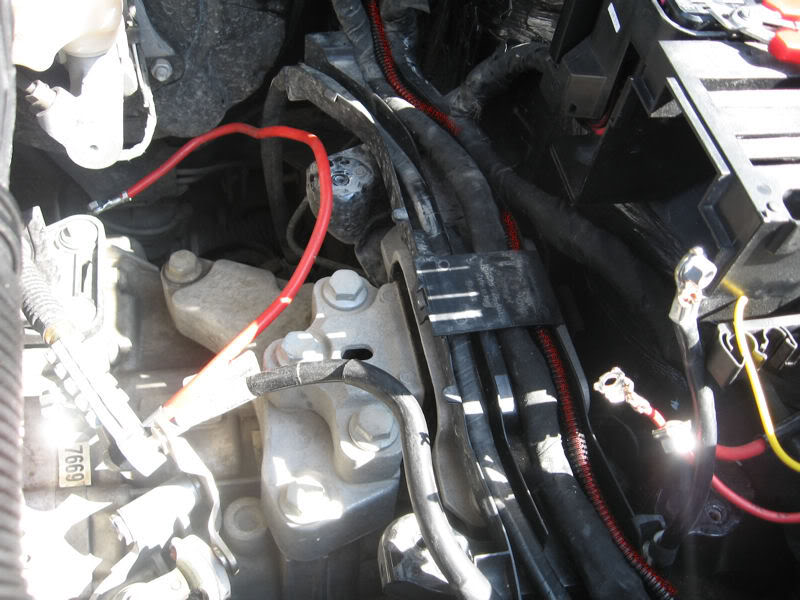
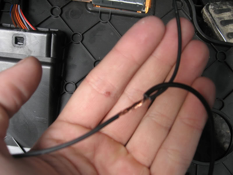
Solder the black power wire to the yellow repair wire we installed earlier:

Locate and remove the 14 pin connector from its holder. It’s located near the coolant hose in front of where the battery used to be:

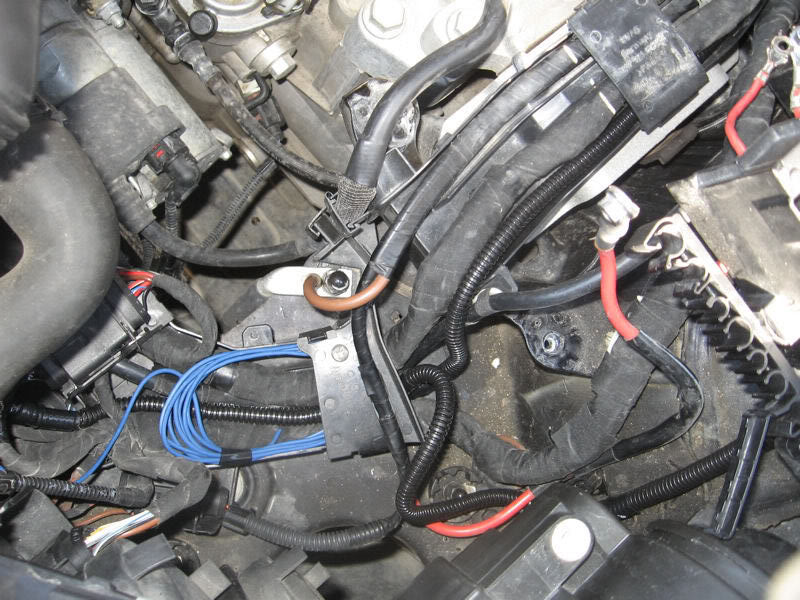
Strip wire, attach green wire from the DO controller, and then solder together. The wire is the Lilac/Green wire in pin 14:
The wiring in the engine compartment is now complete. The blue wire pictured below will be run to the pump in stage 2:
Reinstall the relay panel, battery tray, and battery:

Step 7, Connect relay and ground:
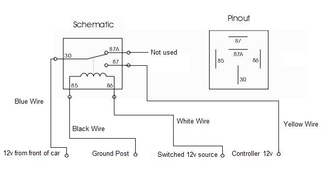
Here is the circuit diagram for the relay. The colors of your wires may be different:
Remove the kick panel to access the ground post. Instructions can be found in the sub install DIY http://forums.vwvortex.com/zerothread?id=3250572. Once the panel is removed attach the ground wire to the post, this wire runs to the DO controller. Once complete reinstall the kick panel:
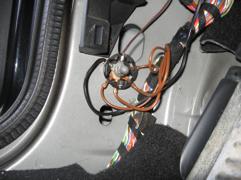
Remove a section of insulation from the ground wire going to the controller and splice in the black side from the relay:
Attach the white wire from the relay to a 12v switched source. The black wire in the picture goes to my radar detector:

Cut the black (used to be pink) positive wire and attach one side to the yellow wire from the relay and the blue wire to the other side:

I drilled 2 holes into the cubby near the steering wheel and attached a zip tie to keep the controller from moving too much:
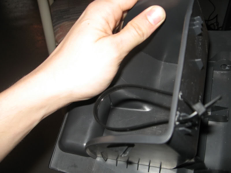
Secure the relay to the existing wiring above the black cover using electrical tape, re-install the black cover, the cubby tray and this stage is complete.
Check out the PDF above for the rest of the install.
*Edit: Sept 25/2017 updated links
-Cad
Here is a link to a PDF version of the DIY: PDF
Here is the first section of that PDF:
After considering all the WM kits I decided on the DO Stage 2 kit.
The Snow performance was 2nd place but in the end I decided on MAP controlled over MAF controlled because the temperature in my city can change drastically in a matter of hours. The free check valve, a metal nozzle holder and black tubing are also a plus.
I considered the AEM kit but I did not want to run any boost lines, I’d rather have it electronic.
I wanted the install to be as clean and stealth as possible, I didn’t want any exposed wires, no fuse holders visible, etc. I opted to solder all the connection instead of using the Posi-Lock connectors.
Devils Own Stage 2 WM kit 2.5bar:
Stage 1, Wiring:
Tools:
T25
T30
8mm socket
10mm socket
13mm socket
Electrical Tape
Soldering Iron
Tweezers
Pointy tool
Parts:
Repair wire 000 979 242
Zip tie
Step 1, Prepare the controller:
The gray wire is not needed as I plan on using the MAP sensor on the engine instead of using an external Map sensor:
The pink power wire was not long enough so I switched it to a longer 16 gauge wire. From here on in the pink wire will be black:
ttp://i597.photobucket.com/albums/tt53/cadbury204/WM/IMG_2946.jpg[/IMG]
Step 2, Remove battery and tray:
The removal of the battery is self explanatory. You will need a 10mm wrench/socket to remove the cables from the battery. Always remember to remove the negative side first. The bracket that holds the battery down is 13mm (blue).
Once the battery is removed you will need to remove the tray it sits on. There are 3 bolts (red). In the picture below one bolt is not pictured:
Tray removed:
Step 3, Remove relay panel:
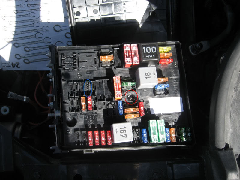
First remove the positive wires from the relay panel. You will need a 10mm socket (red) and an 8mm socket (blue):
Unscrew the T30 screw (red) and the panel should pop off. We will be adding a fuse in F23 (blue):
When I pulled the relay panel off I was working blind I wasn’t sure how this was going to turn out. I had an extra repair wire from when I installed my alarm siren and I found a connector on the back of the panel that fit the repair wire perfectly. I probed around with a multimeter for a few seconds and I found that the fuse above (Blue) connected to the pin 15 on the connector below the panel below (red). This is where I decided to add the 10amp fuse that came with the DO kit.
Step 4, Add repair wire:
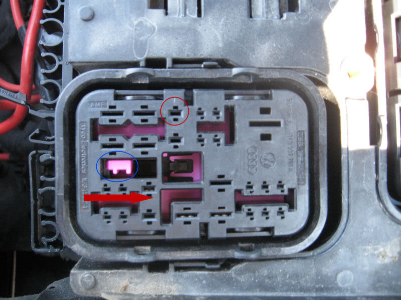
This is the spot where we will add the repair wire. You will need to push the pink clip (blue) in the direction of the arrow:
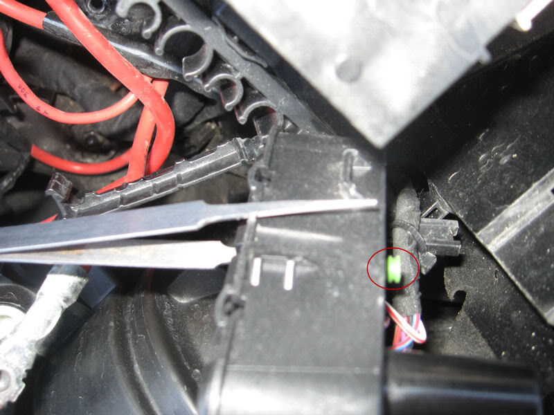
Push out the green water tight plug with the tweezers:
Add silicone to the wire to ensure everything is water tight and insert from the bottom side. VW wanted this panel to stay water tight so once I had the wire in there I double checked that the new wire was indeed water tight. Once completed push the pink clip (2 pictures back) back to its original position:
Step 5, Run wires through firewall:
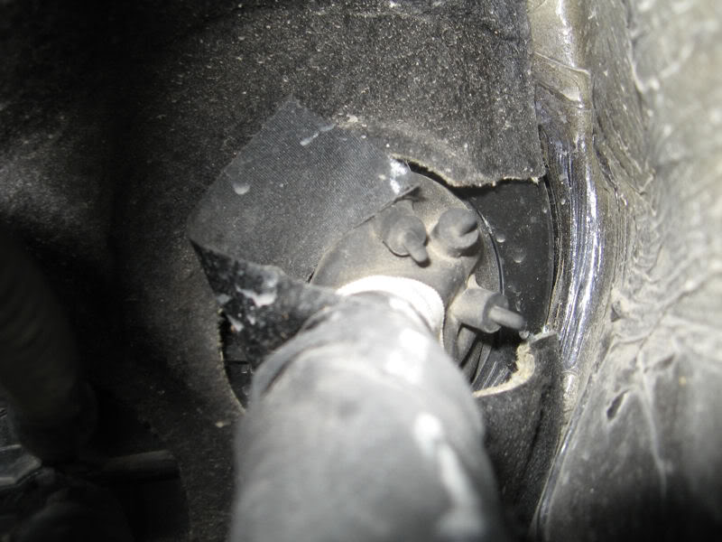
This is the rubber gasket where we will run the wires. It’s located behind where the battery used to be:
Use a long pointy tool and push it through the gasket. You will need to remove the black panel above the pedals to see the gasket from the inside. Remove these 2 screws (red), they are both T25:
The tool:
Wires pulled through from outside:
Wires on the inside:
Step 6, Run wires inside engine compartment:
Put the 3 wires into the wire loom supplied with the DO kit and run it next to the other wiring harnesses (red):
Solder the black power wire to the yellow repair wire we installed earlier:
Locate and remove the 14 pin connector from its holder. It’s located near the coolant hose in front of where the battery used to be:
Strip wire, attach green wire from the DO controller, and then solder together. The wire is the Lilac/Green wire in pin 14:
The wiring in the engine compartment is now complete. The blue wire pictured below will be run to the pump in stage 2:
Reinstall the relay panel, battery tray, and battery:
Step 7, Connect relay and ground:
Here is the circuit diagram for the relay. The colors of your wires may be different:
Remove the kick panel to access the ground post. Instructions can be found in the sub install DIY http://forums.vwvortex.com/zerothread?id=3250572. Once the panel is removed attach the ground wire to the post, this wire runs to the DO controller. Once complete reinstall the kick panel:
Remove a section of insulation from the ground wire going to the controller and splice in the black side from the relay:
Attach the white wire from the relay to a 12v switched source. The black wire in the picture goes to my radar detector:
Cut the black (used to be pink) positive wire and attach one side to the yellow wire from the relay and the blue wire to the other side:
I drilled 2 holes into the cubby near the steering wheel and attached a zip tie to keep the controller from moving too much:
Secure the relay to the existing wiring above the black cover using electrical tape, re-install the black cover, the cubby tray and this stage is complete.
Check out the PDF above for the rest of the install.
*Edit: Sept 25/2017 updated links
-Cad
Last edited:
")