MKV GTI brake position switch
The brake switch and position sensor is located on the brake master cylinder on the passenger side. The switch is a 4 wire sensor with a light switch side and a position sensing side for ABS and ESP control. The hall sensor is a transducer that varies its output voltage in response to a magnetic field. The Hall element is combined with circuitry that allows the device to act in different output modes and provides an analog signal output while the switched side provides a digital on/off signal.
Signal testing
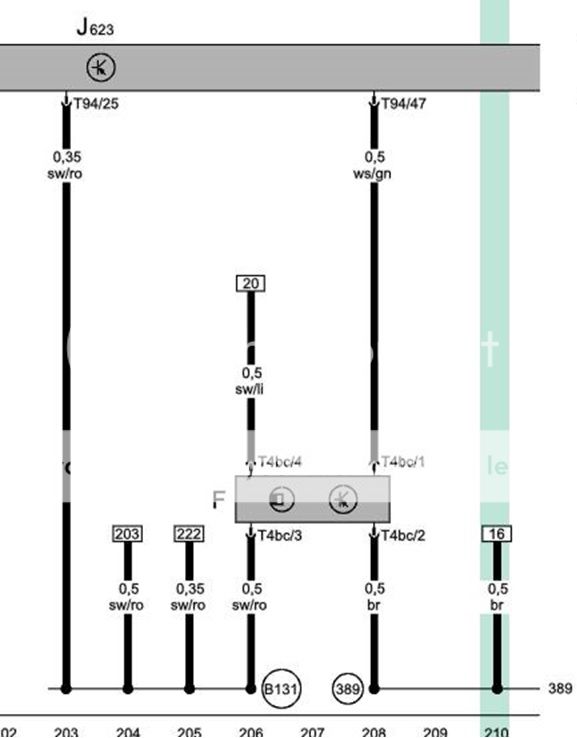
Position sensing side: Pin 3 (black/red), Pin 4 (black/purple)
1. Key ON vehicle
2. Backprobe with “T” pins into connector terminal 3 and 4. Measure voltage with brakes in normal position and record voltage.
3. Measure voltage with brakes depressed and record measurement. Make sure voltage sweeps are consistent and are repeatable.
Brake switch side: Pin 1 (white/green), Pin 2 (brown)
1. Make sure key is in OFF position
2. Backprobe the connector with “T” pins.
3. Check resistance between pins 1 and 2. After applying brakes, one way should show open (O.L.), the other should show closed (<0.5V).