Do not know anything about "Helix LED plug and play tail lights", BUT,
if they are really plug and play for US cars, then No.
The coding is for euro tails with euro wiring.
Installing euro Amber turn signals on a US mk5 Gulf variant involves
adding two additional wires from the controller, one to each tail light,
basically converting the standard US wiring (3 wire)
to the standard euro wiring (4 wire).
So the coding is going to apply to the euro wiring, not stock US wiring.
US mk5 GTi after modification to euro wiring (4 wire)
This isn't entirely correct. I modified the internals of OEM Euro R32 tails and the coding of my 2006 GTI as detailed in the beginning of this thread a few years ago and have had error free amber signals without adding or modifying the rear lighting harness.
There you go, the missing wire is for the amber turn signals that are not present on NAR cars.
Correct.
Depends on how you choose to route the new wires.
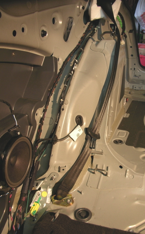
You must add a wire from each tail light to the controller under the dash, left side.
Some people just tuck the new wires under the trim, minimizing trim removal.
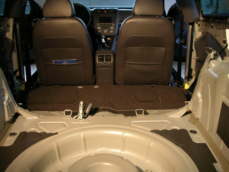
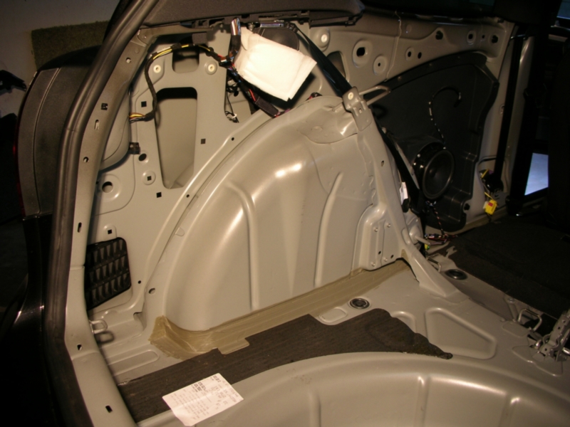
I chose to run mine with existing wiring bundles, which is a lot of work,
as most of the interior must be stripped to do this.
I will say my wiring has remained bulletproof for over 190,000 miles now.
BTW euro r32 tails and euro LED tails are wired exactly the same (coding is different).
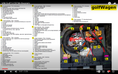
Looks like a lot of work but worth it. I had a couple of questions. I found a diagram of the CECM (central electronic control module) (first attachment) and was wondering if you could clarify where to pin the two new wires. From the picture I've attached, it appears the important connectors and terminals are the following:
B 12 pin connector
#5-right brake light bulb
#9-rear right light bulb
#10-rear right turn signal bulb
C 12 pin connector
#2-left brake light bulb
#10-rear left light bulb
#11-rear left turn signal bulb
So, before I've even looked under my dash, I'm assuming the two new wires will be pinned into connector B at slot #10 and connector C at slot #11. If that is correct, then the other question is which slot on the other end of the wire harness (the connector that goes into the tail lights) does the new wire go into? I'm assuming you have to do some shuffling around. I did find another diagram (see second attachment) but this was for a mod that involved splicing a new wire into the existing brake light/running light wire and then relocating the "blinker" wire. Then doing the long coding of changing the second "14" byte to "00". But, I'm not sure that will work with the way you did it. Please let me know. Thanks.
This isn't entirely correct. I modified the internals of OEM Euro R32 tails and the coding of my 2006 GTI as detailed in the beginning of this thread a few years ago and have had error free amber signals without adding or modifying the rear lighting harness.
I believe this will technically work the way you did it or the way others do it by splicing the wire harness rather than modifying the internal circuit board of the bulb holder. However, the one problem you will likely run into is that you will not get a "bulb out" warning light unless both the bulbs go out for the brake/running lights. If only one goes out, the car won't know because the splice makes the signal still go through the entire circuit. Only if both bulbs happen to go out will you get a warning light. Not a big deal, but not the way it was intended to work by VW. By adding an additional wire from the control module, you can keep the functionality the way it was intended by VW.
Have you added the fourth wire for each taillight?
NAR a5g (mk5 Rabbit, GTi,r32) cars are only supplied with three wires to each tail light.
ROW a5g are supplied with four.
So if you change your coding to ROW settings
without adding the fourth wire and re-pinning to ROW specs,
you would expect a Bulb Out to occur.
:iono:
Not sure if this thread is even active anymore but my question is, when you apply the European long coding, does it also force the passenger side reverse light in to "rear fog light" mode? I'm hoping to add the amber turn signals but keep the TWO reverse lights.
Well since I've been doing this for many moons I figured I'd share my knowledge gained with the rest of the community. I've done a full write up on my DIY amber signals and will be adding it to here, with pics and all. Enjoy and have at it if you'd like.
Supplies Needed
1) OEM bulb holders
2) 194 bulb sockets (I get mine off ebay from a michigan seller)
3) Wire strippers
4) Good pair of cutters (preferably flush side cutters)
5) Sharp razor/utility knife
6) Solder iron
7) Solder
8) Vag-Com (or access to one)
Process
The first thing you want to do is obviously start out with your OEM bulb holder. To get to it, you remove the 2 nuts that hold the outer tail sections on and remove the tail and harness. Once the tail is out there are 3 tabs that hold on the OEM bulb holder. Be careful because they are slightly fragile. I usually start with one of the side by side ones, and then do the outer one, then the second side by side. Comes out easy that way.
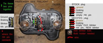
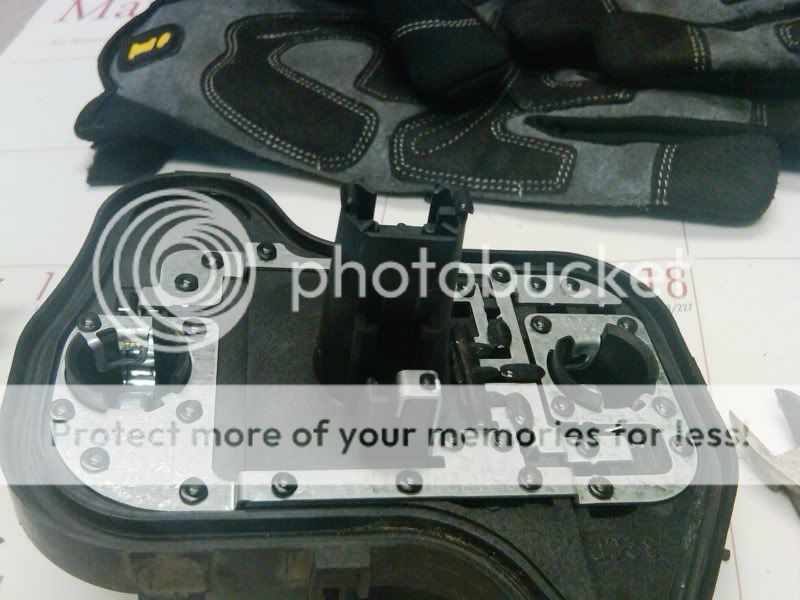
Here's what you got after the bulb holder is removed...
As you can see it's already set up for a bulb, there's just no bulb holder there nor any wiring per say. The metal tabs certainly go to the center bulb area though, so that makes life easier for us modders.
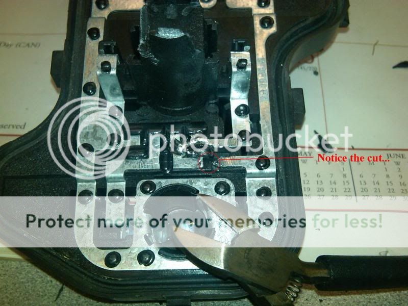
First step is to remove the bits on the middle section that get in the way. This is where you need a good sharp set of cutters. I like to use side cutters because there's less residual crap to trim away when you're done cutting.
The first cut will consist of removing the side portion of the plastic that's in the way. Cut near the "walls" and it will pop right off. If you look at the first picture, you'll see the bit I'm talking about compared to it being removed in the pic below.
After that part is gone, the second cut consists of cutting away the small "fins" on the sides. Again, cut close to the wall and they should pop off pretty easily. There's a total of 4 of these fins, 2 on each side. Here's how it looks when that's done.
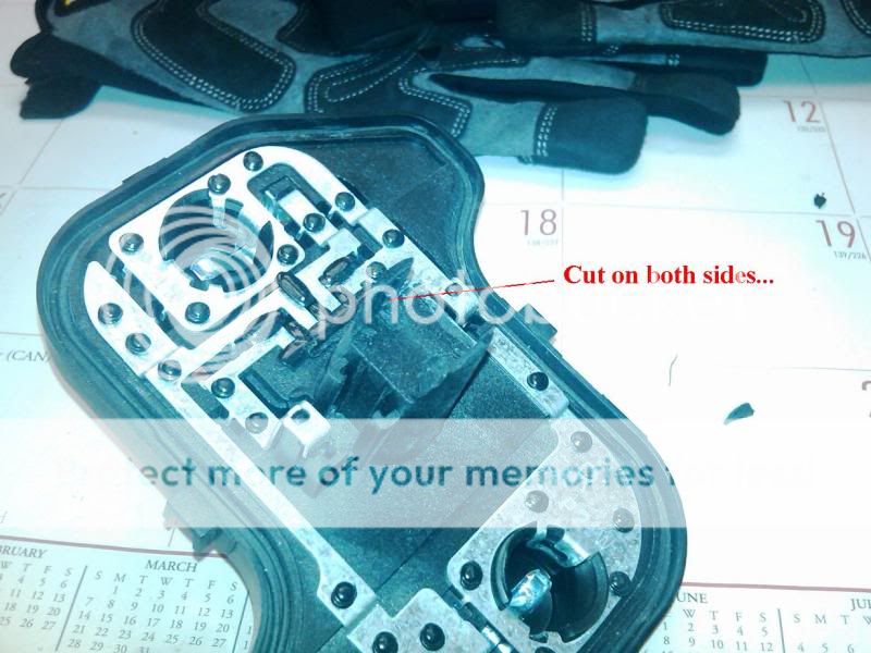
Last cut is to remove the remaining bits inside of the bulb holder area that are on the side walls. There are bits on both sides so make sure to cut them both. These are a bit tricky as they are thick plastic, but again, close to the wall and small bits at time should get them out nicely. Here's the result.
Now take your razor or utility knife and carefully remove any remaining plastic that is left behind. Basically you just want the two "walls" left behind without anything protruding and causing the bulb holder not to fit.
The bulb holders I use I get off Ebay from a seller here in Michigan. They will fit any type of standard wedge bulb. I use Sylvania 921NA LL bulbs. Lots of light output and long life is good. Here's the bulb holders I use and how I receive them.
If you notice, there is a small nubbin on the bottom of the bulb holder. Use your razor knife or cutters to get rid of that. Just be careful not to cut the wires.
After the bulb holder is ready, test fit it into the center portion of the bulb holder. Not any fitment issues and trim the area if needed. You want the bulb holder to sit almost flush with the bottom of the holder assembly.
After you have a good fit, you'll want to trim the wires down so they aren't overhaning the metal tabs as that's were we will be soldering the wires to. The following is an illustration of what I'm speaking of.
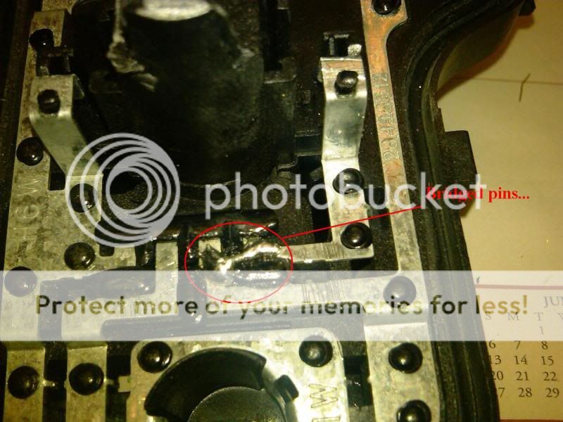
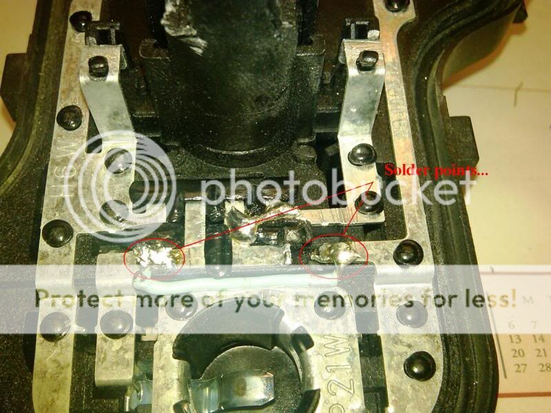
Once the wires are cut, put the bulb holder aside and keep the left over green wire, as you'll use this later. Next step is to bridge the two metal tabs together. Basically what we're doing in this step is taking the pins that would normally be bridged externally, and doing it internally. This will tie the blinker signal to the amber bulb. Note the orientation of the tabs and bulb holder, make sure you solder the right ones together. You're soldering the single tab coming from the middle riser to the tab next to it. Here's an illustration.
Once the pins are soldered, then we can cut the old routing to the original bulb. This bulb will now function with the other OEM bulb, making them act as one unit as opposed to two. You don't need to cut much, just enough to break the connection. Just make sure to cut AFTER the bridge. Here's how I do mine.
Now we can add the jumper wire for the two OEM bulbs. I use the left over green wire that was cut earlier from the new bulb socket. Solder this wire from the metal tab on the first OEM bulb, to the second OEM bulb. Make sure you solder after the cut you made above, or you'll have all 3 bulbs on one circuit. Here's how I do mine.
Finally, you're ready to add in the bulb socket. Take the trimmed bulb socket, and put it in the OEM assembly center bit again. Solder the two wires coming from the bulb socket (green and black in this case) to the two metal tabs on the plastic risers. It should look like this when you're done.
Now pat yourself on the back for a job well done, but don't think you're out of the woods yet. Next step is to test it. Go plug your bulb holder assembly back into your tail harness and turn on the hazards. Make sure they blink correctly. Next, turn on your running lights and make sure they work as well. Don't be alarmed if the amber bulb comes on dimly when your lights are on, as we still have to Vag-Com them to make them work right. If all is well, you're good to go and just need to finish up with the coding. If something isn't right, check all your connections, wires, and solder points and make sure nothing is shorted or disconnected.
Once you've got everything working, you can go ahead with the Vag code. Here's what you need to do for that...
Go into Module 09 (Central Electronics) and take a look at your long coding.
It might look something like this:
14 01 8E 23 40 04 15 00 00 14 00 00 00 14 00 00 00 28 77 0B 5C
We care about the segment that looks like this 14 00 00 00 14
Change the second 14 to 00 so it looks like this: 14 00 00 00 00
Basically change byte 14 from 14 to 00.
By doing this coding you're telling the car's controller that you have Euro spec tails installed. What it does is turn off the running light portion of your second "pin" on your bulb holder. This means that the amber light ONLY comes on when your blinkers are on, and no other time. The brake lights still function as dual roles, both as running lights and brake lights. The way it works now, you'll have full outer circle running lights in red, full outer circle brake lights in bright red, and small inner circle ambers for blinkers.
Conclusion
I've done some 20-25 sets of these bulb holders myself and have improved upon the process throughout that time. This DIY uses my latest and most effective/clean way to do this. The good thing about doing the modding internally is that you don't have to splice any of your wiring or mess with the harness. Plus the way I did this, by adding a bulb holder, means you can always change out a burned out bulb easily. Hopefully this helps some folks who want to try a relatively simple DIY that makes a pretty neat difference.
Not sure if this thread is even active anymore but my question is, when you apply the European long coding, does it also force the passenger side reverse light in to "rear fog light" mode? I'm hoping to add the amber turn signals but keep the TWO reverse lights.