JetTurbo
geezer
- Location
- South Florida, USA
- Car(s)
- 2018 GTi Autobahn 6M
adding a 5A power circuit to Fuse Box C (using vacant slot, not add a fuse)
I recently added a couple of 5A power circuits to the fuse box on the left side of the dash. Thought I would pass along what I learned.
----
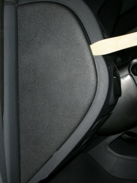
Pop off the fuse panel cover on the left side of the dash board using a trim tool or similar.
Warning: VW adjusts its fuse box layout regularly, your box likely is a different layout.
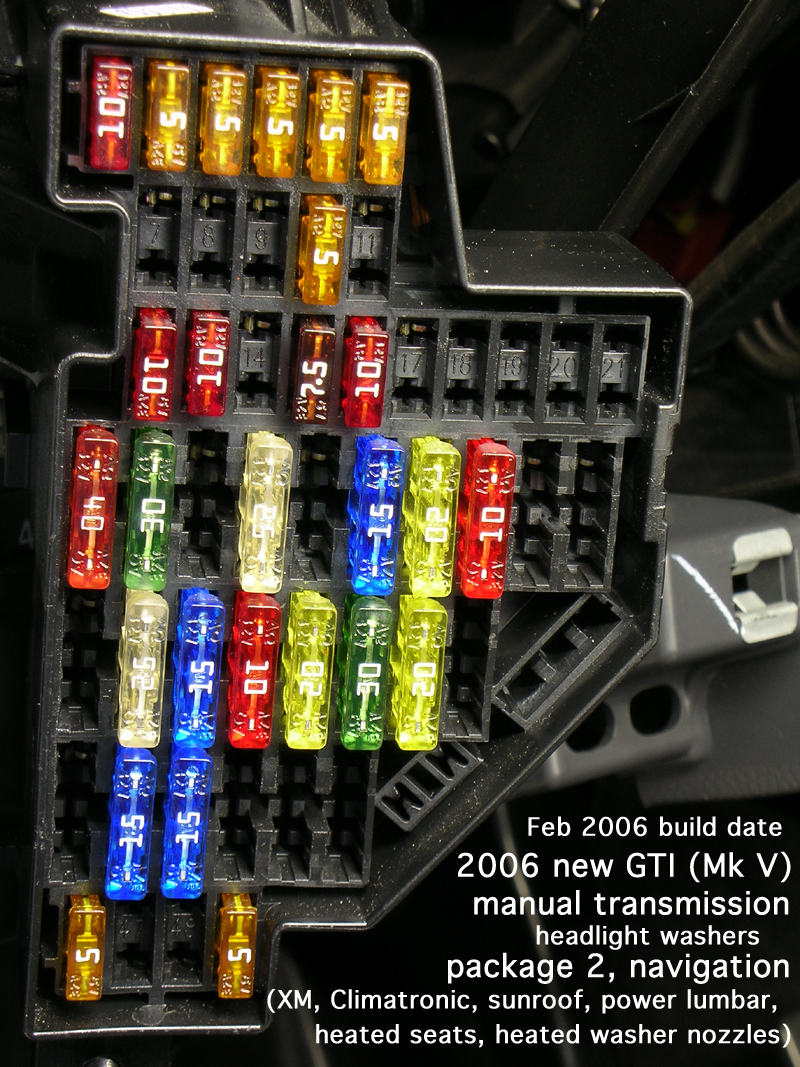
In the above picture you can see unused fuse positions that have the B+ terminal in place
(i.e. Fuse positions 7-8-9-11 (switched) and 14-17 (unswitched).
All that is needed is to add a terminal for the load side and add a corresponding fuse
to add a new circuit to the box.
Take a photo or carefully record the fuse positions of your fuse block with fuses in place for later reference.
You will need to remove all fuses as part of this process.
To add a 5A circuit, you will need a VW repair wire. A variety of wire gauges are available (see below).
A VW 000-979-021 was used for this post.
One (1) repair wire will be cut in half to provide
two (2) terminal with pigtail (enough to add 2 circuits).

---
added 23-Jul-2010 Repair wire sizes available - Thanks anewman for the reference, thanks my-gti.com for the data
2.8mm terminals - ATM fuse (small fuses)
000 979 021 : 0.5mm wire (used for this post / pictures) (000979021)
000 979 133 : 1.0mm wire (000979133)
000 979 225 : 2.5mm wire (000979225)
4.8mm terminals - ATO fuse (large fuses)
000 979 023 : 0.5mm wire (000979023)
000 979 135 : 1.0mm wire (000979135)
000 979 227 : 2.5mm wire (000979227)
000 979 306 : 4.0mm wire (000979306)
/end addition 23-Jul-2010
---
Remove battery ground terminal.
Remove the fuse box (two T20 torx screws, one each top and bottom).
(I also removed the left side of the dash for better access, but it can be done without.
For info on left dash panel removal, refer to LHD MkV drivers mini-glovebox installation aka Dash Cubby )
Remove the black cable cover on the rear of the box (three release clips)
Remove all fuses!
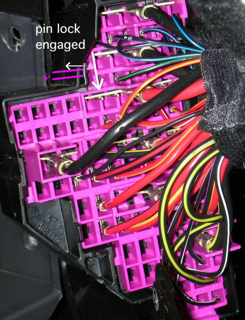
Using a screwdriver gently pry the lock back while sliding the pink terminal housing down in its cover a tiny bit.

This small movement of the pink terminal holder releases the pin locks so that pins can be inserted and removed.
This is all that is needed to insert a new terminal.
(If you wanted to remove a terminal, you would still need a pin removal tool to depress the locks on the pin itself.
This can only be accomplished after the fuse block pin lock is released.)
Insert the repair wire / terminal until it clicks and locks in place.
The spring clips on the terminal itself will lock it in place.
The fuse block terminal lock prevents just those catches from freeing or accepting a pin.
---- Reassemble
Move pink housing back to original pin locked position.
Replace rear cover
Remount fuse block
reinstall original fuses
new terminals circled
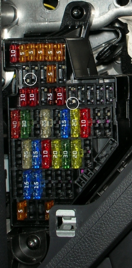
For the 0.5mm repair wire, add a new ATM 5A fuse
in the positions you have activated. (ATM 5A = VW pn N 102 615 01)
Complete - two new circuits added

I recently added a couple of 5A power circuits to the fuse box on the left side of the dash. Thought I would pass along what I learned.
----
Pop off the fuse panel cover on the left side of the dash board using a trim tool or similar.
Warning: VW adjusts its fuse box layout regularly, your box likely is a different layout.
In the above picture you can see unused fuse positions that have the B+ terminal in place
(i.e. Fuse positions 7-8-9-11 (switched) and 14-17 (unswitched).
All that is needed is to add a terminal for the load side and add a corresponding fuse
to add a new circuit to the box.
Take a photo or carefully record the fuse positions of your fuse block with fuses in place for later reference.
You will need to remove all fuses as part of this process.
To add a 5A circuit, you will need a VW repair wire. A variety of wire gauges are available (see below).
A VW 000-979-021 was used for this post.
One (1) repair wire will be cut in half to provide
two (2) terminal with pigtail (enough to add 2 circuits).
---
added 23-Jul-2010 Repair wire sizes available - Thanks anewman for the reference, thanks my-gti.com for the data
2.8mm terminals - ATM fuse (small fuses)
000 979 021 : 0.5mm wire (used for this post / pictures) (000979021)
000 979 133 : 1.0mm wire (000979133)
000 979 225 : 2.5mm wire (000979225)
4.8mm terminals - ATO fuse (large fuses)
000 979 023 : 0.5mm wire (000979023)
000 979 135 : 1.0mm wire (000979135)
000 979 227 : 2.5mm wire (000979227)
000 979 306 : 4.0mm wire (000979306)
/end addition 23-Jul-2010
---
Remove battery ground terminal.
Remove the fuse box (two T20 torx screws, one each top and bottom).
(I also removed the left side of the dash for better access, but it can be done without.
For info on left dash panel removal, refer to LHD MkV drivers mini-glovebox installation aka Dash Cubby )
Remove the black cable cover on the rear of the box (three release clips)
Remove all fuses!
Using a screwdriver gently pry the lock back while sliding the pink terminal housing down in its cover a tiny bit.
This small movement of the pink terminal holder releases the pin locks so that pins can be inserted and removed.
This is all that is needed to insert a new terminal.
(If you wanted to remove a terminal, you would still need a pin removal tool to depress the locks on the pin itself.
This can only be accomplished after the fuse block pin lock is released.)
Insert the repair wire / terminal until it clicks and locks in place.
The spring clips on the terminal itself will lock it in place.
The fuse block terminal lock prevents just those catches from freeing or accepting a pin.
---- Reassemble
Move pink housing back to original pin locked position.
Replace rear cover
Remount fuse block
reinstall original fuses
new terminals circled
For the 0.5mm repair wire, add a new ATM 5A fuse
in the positions you have activated. (ATM 5A = VW pn N 102 615 01)
Complete - two new circuits added
Last edited: